


Posted 19 June 2020
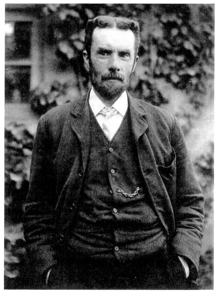
The first known patent granted for coaxial transmission line was a British patent in 1880 to Oliver Heaviside, a self-taught British electrical engineer. Heaviside’s coaxial cable was a copper tube, which formed the outer of the line. The inner concentric (coaxial) conductor was a copper wire which was supported by insulating discs to keep the central wire a constant distance from the inner of the copper tube. The major dielectric was air, giving low loss to signals travelling along it.
The term coaxial (often abbreviated to co‐ax) is derived from the inner conductor and outer conductor (screen) sharing the same axis. Coax cables were originally designed for Radio Frequency (RF) and microwave transmission. The signal is transmitted through the cable at high frequency as a wave and is guided by the conductors. The outer conductor also prevents electrical interference getting in or out.
Types of coax and applications:
RG stands for Radio Guide and was invented by the U.S. military in the 1930’s. The number given to the coax (e.g. RG59) is the next one of the pile, there is no relation between the cable and the number.
Any revisions to this were suffixed with a letter. RG59 became RG59A/U and then RG59B/U. The “U” means military utility grade. In the mid 40’s this system was superseded by the mind boggling “Mil Spec” system and coax was categorised as MIL‐C‐17. Within this coax is categorised by a number so RG59 is now MIL‐C‐17G/29. In practice 90% of industry has stuck with using the RG reference.
Many RG cables have been adapted for commercial use and can be a long way from the original Military specification. “Commercial” RG6 is normally a low quality foil and braid cable whilst Milspec RG6 has a silver plated copper braid under a plain copper braid.
URM is the UK equivalent to the American “RG” system. There are many coax cables that are often interchangeable such as URM67 and RG213. URM is an abbreviation of Uni‐Radio Metric. Like many RG cables there are lots of “commercial types” available in the market that are some way off the true product.
CT “Copper Tape” Coax cables were designed by Radex for digital video applications. They provide high quality satellite TV transmission. The design utilises a thick copper tape with a low braid coverage and were designed for F type connectors. Due to the low braid coverage fitting other types of connector can be problematic. There are many poor quality “look alike” cables in the market at low prices. FS Cables stock “TV” series and Webro WF which is comparable to the CT original.
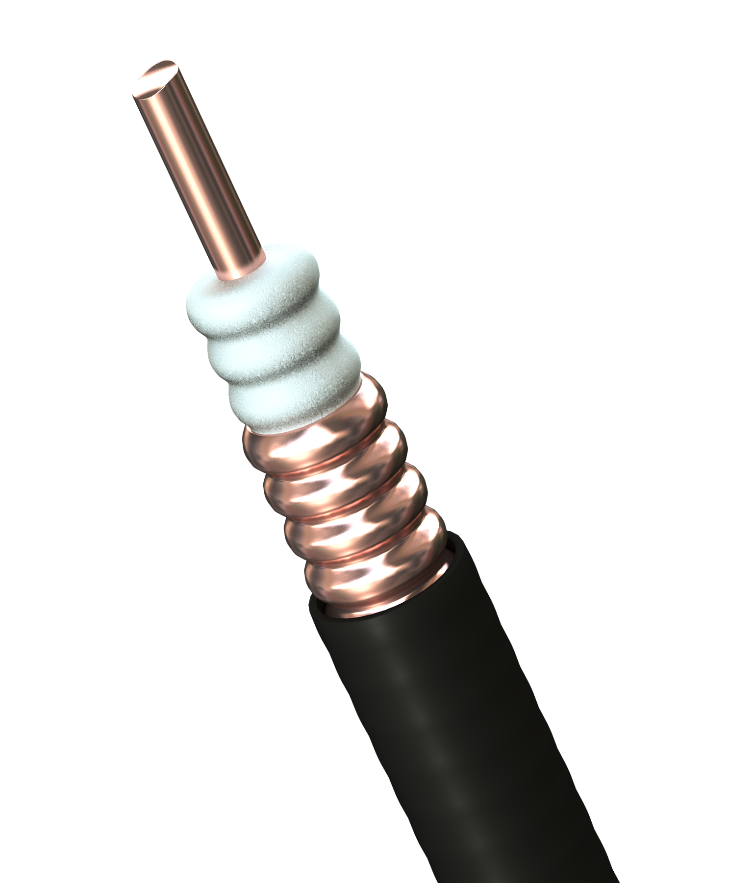 Corrugated Low Loss Coax cables are used when a large amount of power is required to move information long distances between the transceivers. The cable runs to the dish tend to be quite short. Typical applications are international communications infrastructure and military communications. Normally they would run to and from satellite and microwave dishes. Alternative uses include very long cable runs where signal loss must be minimised such as through tunnels.
Waveguide cables are also used on very large microwave systems. These normally consist of the corrugated copper tube and sheath without a centre conductor or dielectric.
Broadcast Coax cables are many and varied. Most are high specification designs incorporating double braids and silver plaiting to ensure low signal loss and good connectivity. Tri‐Ax cables are also used in this environment. They have a third braid separated from the first two by an additional dielectric; this can be used as additional screening or an addition transmission conductor.
BT, RA & TZC. These types of coax are normally 50 ohm and are used for interconnections within telephone exchanges. There are a variety of options and sizes including multicores (2, 4, 8 & 16). BT and RA are British Telecom standards and TZC is Ericson standard. Both types are widely used around the world.

Antenna Feeder cables are used in the mobile phone and microwave communications. The conductor can be solid copper, CCA or hollow tube depending on the size. Screens normally consist of aluminium foil & Tcu braid. The market leading brands are Times LMR and Andrew Cinta. We market Antennax Brand which is a high performance alternative.
Inside a coax cable:
A coax cable consists of an inner conductor, dielectric (insulation), screen and sheath. There are many variations to these components:
Inner conductor types:
Some coax’s use higher resistance metals (or no metal) as the centre of the inner conductor. It does not have a detrimental effect to the signal in RF/ Microwave as the signal travels along the outside of the conductor, not the centre. This is called skin effect.
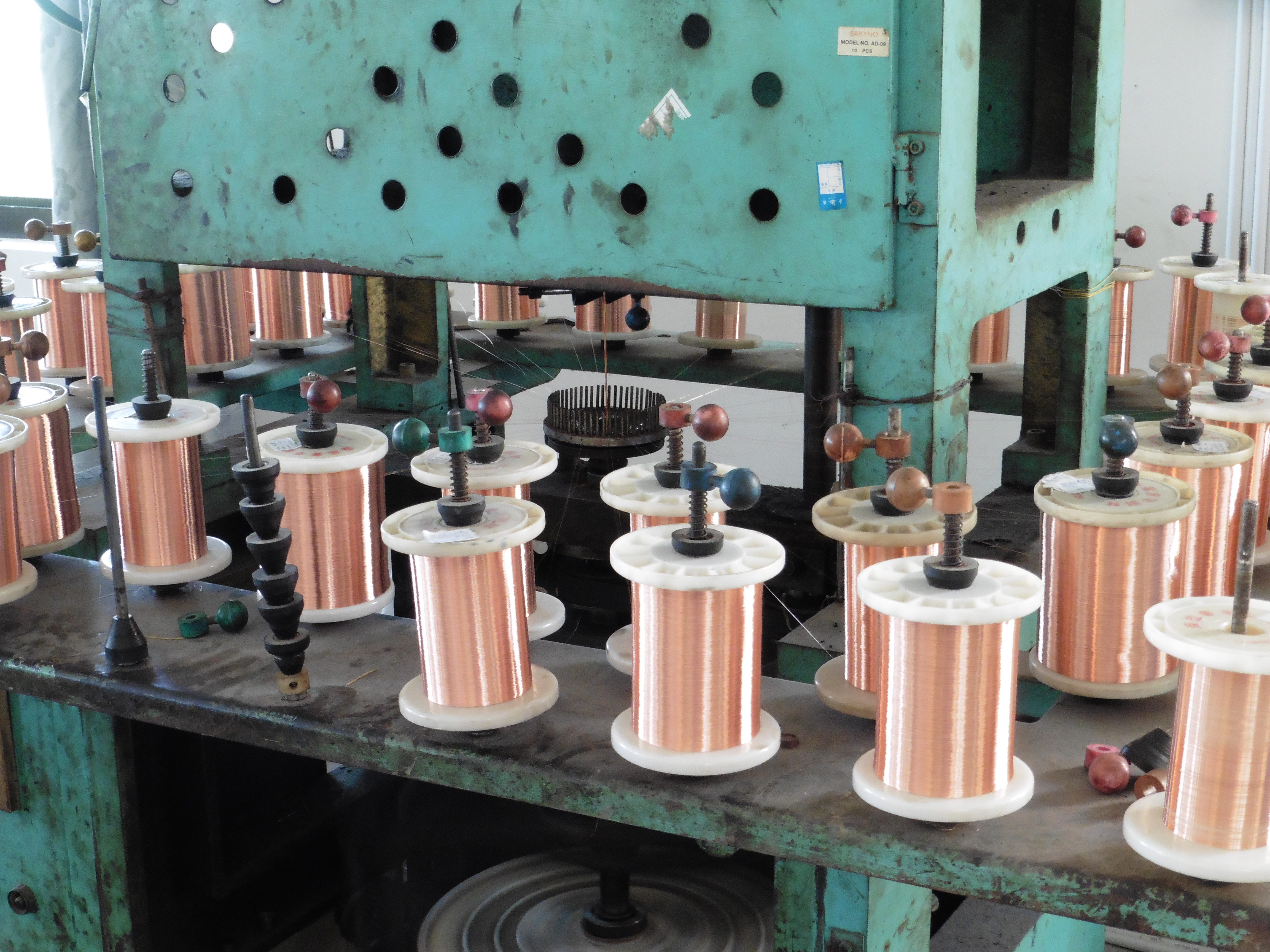
Plain copper: This can be solid or stranded and is often used for small cables to achieve low electrical resistance.
Plated copper: As above with the addition of tin or silver plated copper to increase conductivity at termination.
CCS: Copper Clad Steel. A layer of copper is bonded around a steel inner conductor, trade name copperweld. In RF applications this design combines the tensile strength of steel with the electrical properties of copper due to “skin effect”. Silver plated versions are also available ‐ SCCS
CCA: Copper Clad Aluminium. A layer of copper is bonded around an aluminium inner conductor. This method reduces cable weight and cost compared to solid copper conductors.
Copper tube: Hollow copper tubes are sometimes used for inner conductors on large coax cables to save weight and cost.
Dielectric materials:
Polyethylene: LDPE is most common due to its low capacitance and good electrical insulation values.
Foamed PE: FPE is Polyethylene with lots of tiny air bubbles in it. This improves the capacitance values and reduces signal loss. PE can be foamed in two ways:
1) Chemically by including an additive in the PE material at extrusion. This is difficult to control and can lead to a variable density of dielectric which can in turn affect the cable performance.
2) Physical foam, also called gas injection. Nitrogen gas is injected into the extruder head to create the “air bubbles” in the PE dielectric. This is much more controllable than the chemical process and prevents shadowing.
PE Cellular: PEC looks like a “cartwheel” with a conductor coming out of the centre. As there is lots of air in the cable and air is a superb dielectric material, it is very low loss however it can let water through the cable creating performance issues. Example Original style CT100.
PE Airspaced: PEAS dielectrics have a “string” of PE wrapped helically around the inner conductor to support it inside the cable without touching the outer conductor. By using air as the dielectric signal loss can be ultra-low.
PE Semi‐Solid: PESS dielectrics also have a “string” of PE wrapped around the inner conductor, this is then supported in a PE tube. The performance is not as good as PEAS but the cable is physically more robust. Example: RG62.
Teflon: PTFE, FEP, ETFE and PFA can all be used as dielectric materials. They can be manufactured to achieve similar performance as more traditional cables whilst offering reduced size and weight. They are also selected for their high and low temperature abilities. Some Teflon materials can be foamed to improve performance further.
Screens/ Outer conductor:
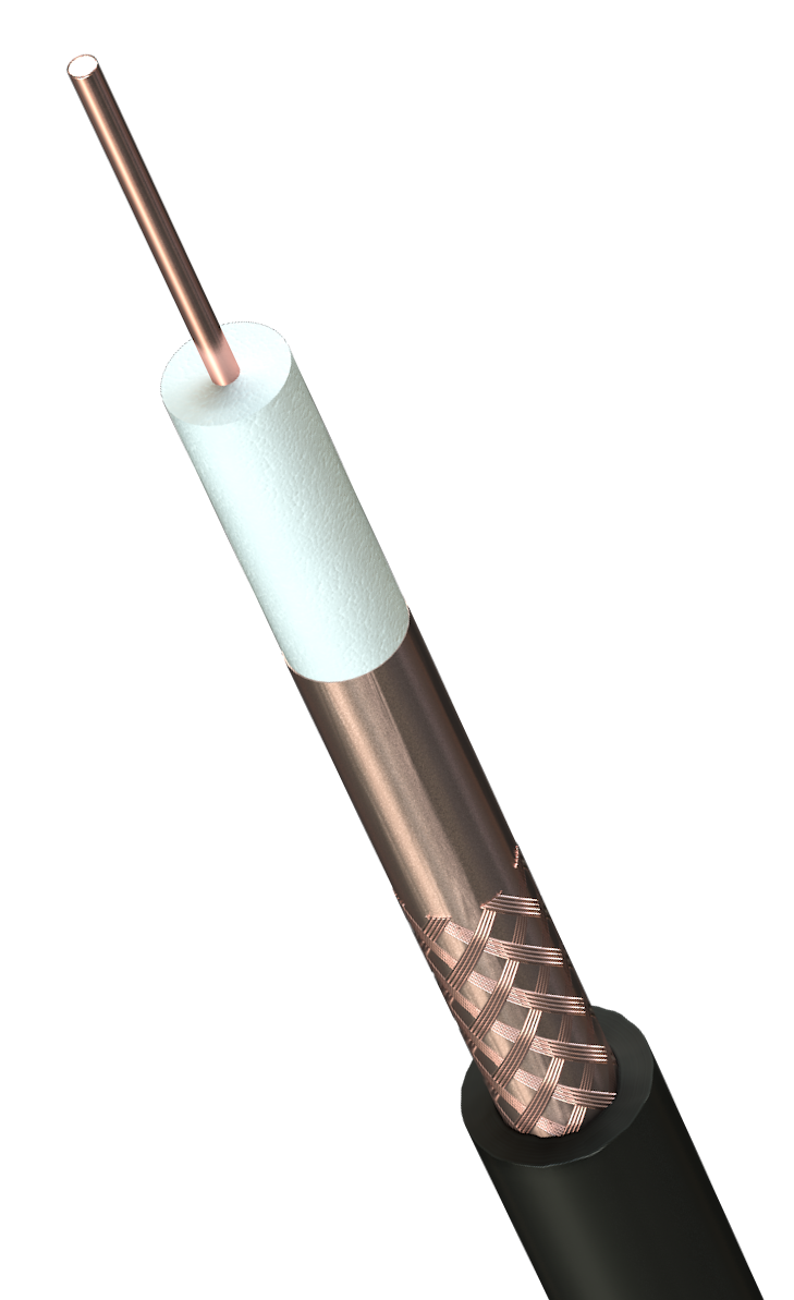
Copper braid: These can be plain copper or plated with tin or silver to improve connectivity. Some cables have double braids to improve performance.
Aluminium braid: To reduce weight and cost aluminium braid are used. Due to the higher resistance of aluminium this can reduce performance. Aluminium and CCA are often found on budget grade coax cables to reduce cost.
Aluminium braid: To reduce weight and cost aluminium braid are used. Due to the higher resistance of aluminium this can reduce performance. Aluminium and CCA are often found on budget grade coax cables to reduce cost.
Foil & Braid: Variations include copper tape & copper braid (bare or plated), aluminium tape & copper braid and aluminium tape & aluminium braid (or CCA). Adding tapes can enable the braid coverage to be reduced whilst maintaining effective performance.
The composition of the braid can have a large impact on both cost and performance. Variations include: Braid coverage, normally measured in %. Individual wire diameter (thickness) Braid pitch (The angle that the strands cross) and metal type.
Corrugated Cu: This is a thick copper tube that has corrugations to allow it to bend for installation. They are normally used for microwave transmission (e.g.: mobile phone masts) where High power (kw) is required to launch the signal.
Electrical properties and terminology:
Impedance is the total opposition that a circuit offers to the flow of an alternating current at a given frequency. It is measured in Ohms and is a ratio of voltage to current over an infinite distance. (This is why impedance (Ohms) is not suffixed by a linier unit.) Although many different types of impedance exist for coax the most common are 50 Ohm (microwave) & 75 Ohm (Video).
To change the impedance of a coax the material or thickness of the dielectric must be changed. As a “rule of thumb” the thicker the dielectric material relative to the inner conductor diameter the higher the impedance and the thinner the dielectric relative to the inner conductor diameter the lower the impedance.
Capacitance is the ability of a dielectric material (insulation) between conductors (a coax inner conductor and screen) to store electricity when a potential difference exists between the conductors. This is measured in pico Farads/metre (pF/m) or nano Farads/m (nF/m).
Velocity of Propagation (VP) is the speed that electric energy travels through a length of insulated cable compared to the speed it would travel in free air. This is expressed in percentage with the ultimate goal being 100%.
Inductance is the property of a circuit that resists a change in current flow. This causes current changes to lag behind voltage changes and is measured in henrys.
Resistance measures the “difficulty” in moving electric current through a conductor and is measured in Ohms/km (or Ohms/kft if you are American). Resistance is always measured against a linier unit.
Attenuation is the decrease of the power of a signal between two points. It is measured in decibels per unit length at a given frequency.
Power rating (or handling) is proportional to the ability of the cable to dissipate heat. Heat is generated due to electrical losses in the centre conductor and screen during operation. As a result the power rating is limited by the operational temperature of the dielectric. Power rating is measured in kW (kilowatt).
Coax Connectors:
There are a wide range of connectors available for coax cables with different body sizes and methods of termination. The type required is determined by what the equipment that you want to connect to. Just like a cable, impedance matching is critical. Different parts of industry have adopted types that favour their application.
BNC. This fixes by a bayonet fixing and is the most common for CCTV and commercial applications.
TNC. The body is the same as a BNC but has a screw on fixings and are used where vibration can be a problem such as aircraft.
UHF connectors were very popular with the Military and radio broadcast. They have a threaded connection and are very similar to an N‐type. The N‐type as tended to supersede UHF connectors due to its improved design and better impedance stability.
N Types are normally 50 ohm and used in RF applications. They are high quality and offer good connectivity with low loss.
F Type. These are a “cheap and cheerful” connector mainly used in the Satellite TV market. They connect by a fine threaded screw mounting and normally do not have a centre pin using the solid centre conductor instead.
HDC T43 connectors are used for terminating telephone coax cables (i.e BT3002 & TZC) in distribution racks. Their compact design allows for high density termination within the rack. HDC – High Density Connector. Sometimes they are gold plated.
Electronics connectors are high quality and precision made. They can be found test equipment and communication units. Types include SMA, SMB, SMC and many more! These also can be gold plated.
All connectors are available in male and female form. Normally the male is the plug (and has the centre pin) and the female is a jack. The exception to this is some of the micro telecom & electronics types. It is best to check these individually.
All connectors are available in male and female form. Normally the male is the plug (and has the centre pin) and the female is a jack. The exception to this is some of the micro telecom & electronics types. It is best to check these individually.
Many adaptors are available including plug to plug and jack to jack to enable connection. These can be of the same type (BNC to BNC) or crossover (BNC to N type etc.). On all connectors the front end of a connector is always the same size regardless of what cable it attaches to. The centre pin back body and ferrule are the parts that are adjusted to take different cables. A BNC plug will fit any BNC jack around the world.
Cheap connectors will be die cast (made in a mould) from zinc. Many BNC connectors are zinc and are fine to fit to the back of a CCTV camera that will be in place for years. For high quality connections where signal loss is unacceptable or for mobile equipment that can be assembled and disassembled regularly solid brass is used. These are turned from brass rod and plated in nickel or silver to increase connectivity.
So, there you have it, if you need any other information or have any questions just drop us a line or speak to one of our technical sales team on 01727 840841.


